Archive for the ‘microcontrollers’ Category
PlugIn Board – An AVRISP breakout board for prototyping with the AVR microcontroller
In the past I would connect AVR microcontrollers to the AVRISP programmer by using individual wires to connect the 6×2 IDC connector to the protoboard. There was also the hassle of wiring up a 5v supply. So I designed the PlugIn Board to quickly connect the AVRISP programmer to AVR microcontrollers on a protoboard.
Layout
Looking at the PCB Board Layout below, the PlugIn board takes the AVRISP 2×3-pin IDC connector (ISP1) and maps to a 0.1-inch in-line header that plugs into a protoboard. In addition it can power the AVR. Unregulated power can be fed through a 2.1mm DC jack or screw-down terminal connector(J1) which is connected to a 7805 regulator(IC2) to provide 5V to the AVR and other circuits.
A few other features in the PlugIn board is it has the recommended 10kOhm pull-up resistor(R1) for reset and the pinout matches the ATMEGA32 programming and power pins.
PCB Board Layout
Future Improvements
If I were to do another iteration of the PlugIn Board I’d add the recommended decoupling circuitry for the ADC with a separate ground plane as outlined in the Atmel AVR design considerations app notes.
While not recommended due to the long signal path, I’d also include a header for an external clock. It would allow the user to swap out crystal oscillators or use an external clock source without fiddling around on the protoboard.
PCB Board Files
The PCB is designed using Eagle. The board and schematics are available on my BitBucket at https://bitbucket.org/xyzio/circuits/src/master/PlugIn%20Board/
Final Product
I had the board fabbed at OSH Park. It works well and greatly simplifies programming AVR microcontrollers.

Project Nixie Tube Clock
I become interested in Nixie tubes after I bought a Netduino and tried out the ArduiNIX. From that I decided to make my own Nixie Tube clock. My clock, besides showing the time, also shows the date, year, temperature, has an alarm, and can communicate with a PC via USART.
Hardware
The clock is built on two PCB boards connected by two 10 pin IDC cables. I use stand-offs to screw the two boards together, doing that makes the clock free standing and eliminates the need to build a separate case or stand. I would have done it on one giant board but that was not feasible due to size limitations in Eagle freeware. The boards were manufactured through OSHPark.
I use four IN-17 Nixe tubes for the display. Although they are small, IN-17 tubes are cheap and easy to source through Ebay. Also I had several left over from my ArduiNIX experiment.
The tubes are multiplexed through 2 SN74141 BCD to decimal drivers. I built a version with one driver per tube but that seemed wasteful which is why I decided to multiplex them. I also tried a version where I drove the tubes with individual transistors but the switching was slow resulting in much ghosting.
The SN74141 drivers interface to the microcontroller through TLP-627 optoisolators. I chose an optoisolator to isolate the microcontroller from the tube high voltage. In theory it is cheaper to replace a $1.30 optoisolator than a $8 micro. In my case the optoisolator did not isolate enough and I ended up ruining a MCU in a high voltage probing accident.
The microcontroller is an ATMega32. It is run at 8MHz with the JTAG fuse bit disabled. I originally selected the ATMega32 because it has enough pins to drive four SN74141 tubes and perform serial I/O. In hindsight, for the two drivers I ended up with, I could have gone to a lower pin-count MCU like the ATMega328 and saved some board space. The code only uses 10% of the available 32KB of flash. It is nice to not have to worry about IOs or having to optimize the code to eke out every iota of performance and it leaves room for expansion.
The power-supply is based on the one in the ArduiNIX that I write about here.
The time, date, alarm, and temperature come from the DS3231 RTC chip on my RTC breakout board documented here. I wired up a buzzer for the alarm but I didn’t read the datasheet correctly and wired one of its pins to the input voltage. This leads to a high DC voltage across the buzzer which the datasheet warns again. I’ve fixed this in the Eagle files so it will work when order another set of boards.
The user interface is through three push-buttons on the Nixie tube board. One button is used to switch between the modes and the other two are used to increment the left and right sides.
In addition, I brought out the TX and RX pins for serial communication. I used Dean Camera’s Interrupt Driven USART guide to get the interface up and running but I haven’t done much with it since. It would be interesting to show stock prices and other numerical data from the internet on the display. There are three LEDs available for debug, alarm, and to show seconds.
Software
The code is based around an overflow interrupt on Timer0. The interrupt calls the RTC to get the current time. From that the input pushbuttons, the alarm, and LEDs are toggled once per second.
The display() function drives the digits and uses a state machine to multiplex between them. This avoids wasting cycles in a delay loop to implement a delay between switching displays to avoid ghosting.
UpdateLeftRight() updates the variables that hold the values to write to the tubes with the correct value based on the selected mode. update_time() updates the time, date, day, and alarm based on the mode and which increment button the user is pushing. The RTC data is read through the GetTimeDateAlarmDataFromRTC() function.
I didn’t wire the outputs of the SN74141 to the correct leads on the nixie tubes, Instead I wired them based on ease of routing. remap() remaps the input to the driver to the correct value that should be written to the driver.
In addition, I have ‘anti_flashy‘ code to toggle the digits once per second through all their values per minute. This is done to avoid cathode poisoning that will eventually dim the tubes and also as a way to count the first 9 seconds of each minute. It is a nice effect. And since I don’t have the buzzer wired up, I toggle the debug LED on pin D6 when the time hour and minutes match the alarm.
Things I Learned
Be careful with the high voltage output. I’ve shocked myself a few times by touching the board accidentally in a high voltage area.
Don’t probe around the board with wires hooked up to 170V. I had a case where one of my tubes were not working and I tried powering them directly using very sloppy techniques. Something shorted out and I ended up damaging the neighboring tube, shorting the optoisolator, and burning out the microcontroller!
Use IC sockets as much as possible. Using a socket meant I could quickly replace a burnt out ATMega without having to rebuild a whole board. Not using a socket for my tubes meant I had to re-do the entire display board when I fried one of the tubes.
Read the datasheets and then read them one more time. Not reading the buzzer datasheet and just going off information from the internet meant that I wasn’t able to use the buzzer in my project.
Check your header directions and orientations of the components. Print out a paper copy of your board, place your components on them, and check the pin orientation. I put the tubes on the back of the board in one iteration of the design which meant that I had to re-do the board.
Always have a current limiting resistor in place. Testing my tubes with high vcc and no limiting resistor resulted in them flickering and glowing when off.
Optimization
There is some optimization possible on the board and in the software.
For the hardware, I’ve added a switch to the board to turn off the clock at the input supply for when I’m away and of course fixed the buzzer. There are enough I/O pins open to drive a LCD display to show additional information. This with the serial I/O can give us a nice PC connected display. The MCU is only running at 8MHz but can be clocked at up to 16MHz so there are plenty of spare cycles available.
The timings for reading the RTC and driving the display can be optimized further. Initially I used delays to wait between turning off a tube and turning on its neighbor – you can see this in the commented out code in the display() function. I later took out the delays but did not check to see if I can read the RTC or multiplex the tubes less often. This will save power and free up cycles for additional features and effects.
Additional effects are possible with the tubes. Things like flickering, scrolling, fading in, fading out e.t.c
Special Thanks
For the original inspiration and for sharing their designs:
http://arduinix.com/
Adafruit and Sparkfun for their articles and sharing their Eagle libraries.
For inspiration and samples of code for driving the DS3231 RTC chip:
http://www.elektronika.ba/800/warm-tube-clock-v2-nixie-clock/
Links
All code and files are released as ‘Do what you want with it. I am not responsible for anything that happens.’
My source code:
https://bitbucket.org/xyzio/avr-code/src/master/two_driver_board/two_driver_board/
CPU board schematic:
https://bitbucket.org/xyzio/circuits/src/master/Two%20Driver%20CPU/
Tube board schematic:
https://bitbucket.org/xyzio/circuits/src/master/Two%20Driver%20Tube%20Board/
Pictures

Front

Back

Top view
Video Demo
Driving Adafruit’s RGB Matrix with Python on the BeagleBone Black
I wrote this code to drive the Adafruit 32×64 RGB Matrix using a Beaglebone Black and Adafruit’s IO Python library. The code is super simple – it writes a static color background to the top and bottom halves of the display through the shift registers and triggers the latch. It then iterates through the addresses so the LEDs for that row turn on and then goes to the next address. This should create a background color through persistence of vision.
Along the way I discovered:
The Python Library isn’t fast enough to drive the RGB matrix to provide a persistent display. There is flicker and when updating colors, you see each row turn on and off. You literally see the delay. There are ways to speed up the writes by using the PRU or direct IO writes. But I should not have to do that on a 1GHz processor.
The RGB matrix doesn’t light up unless you continually change the address. This was really annoying when I was figuring things out. I did not find this documented anywhere on the web except on rayslogic’s RGB writeup.
It appears the BeagleBone Black’s IO pins cannot push enough current to turn on the input schmitt triggers. I spent a lot of time being frustrated because I couldn’t get the green and blue LEDs to light up on my board.
Finally I noticed the green LEDs were barely on and had a brightness gradient from low to high address. My guess is the address pin was barely turning on which meant 0 was the most common address – hence the higher brightness on the lower rows. I got around this by plugging the G(reen) input directly into the 5V pin on the BeagleBone Black. Of course this now meant the green LEDs are always on!
Adafruit charges too much for the RGB panels. For example, the seller kbellenterprises on ebay has a 16×32 RGB matrix for $16 including shipping. Adafruit has the same panel for $25 and you pay for shipping.
Adafruit charges too much for male-to-male jumper wires. The seller funny-diy on ebay sells 40 for $1.80 with shipping while Adafruit charges $4+shipping for their so-called “premium” wires. Adafruit needs to rename them to “premium-priced“.
My Python Code:
https://bitbucket.org/xyzio/rgbmatrix/src/master/bb_python/logic.py
Sources:
http://www.rayslogic.com/propeller/programming/AdafruitRGB/AdafruitRGB.htm
https://learn.adafruit.com/setting-up-io-python-library-on-beaglebone-black/overview
Non-Arduino Adafruit OLED Display Library
Adafruit sells a really nice 16×2 OLED display and they even have an Arduino library for it. However I only have a Atmega32 and Arduino does not run on the Atmega32. Rather than spending $20 or so for an Arduino, I decided to port their library to AVR. It wasn’t too difficult since Arduino is just AVR C++ behind the scenes.
Re-writing the Adafruit library was straightforward. I hardcoded PORTA as the I/O port but some additional code could make that generic. I had to re-write the digitalRead and digitalWrite functions to read and write out of PORTA instead of the Arduino pins. The delayMicroseconds command is replaced by the AVR _delay_ms() macro.
The trickiest part was figuring out how to implement the print function. After some digging around I found it in the Arduino code at \hardware\arduino\cores\arduino\Print.cpp. The print function calls a write function that iterates through the character string which then calls our native OLED write on each character. This seems seems a little roundabout but I guess that is how they chose to implement it.

Links:
My No-Arduino code:
https://bitbucket.org/xyzio/avr-code/src/master/characterOLED/
Adafruit Arduino library:
https://github.com/ladyada/Adafruit_CharacterOLED
Youtube demo:
Binary Clock II with ATmega32
I made this binary clock to learn how to use Eagle and go through a real PCB ordering process. Until I made this clock, all my PCBs had been made through ExpressPCB. ExpressPCB’s PCB ordering process is very easy but their PCB design tool is not as advanced as Eagle, puts out proprietary files, and is not well used by the PCB community. In addition their PCBs are a little on the expensive side at $51+shipping for 3 boards although you do get them in 1-2 weeks.
For this project I had the PCB manufactured by BatchPCB – a service run by SparkFun. However, since then I’ve switched over to OSH Park. OSH Park has much better looking and higher quality PCBs than SparkFun. In addition they are purple and come with nice looking gold plating.
Layout:
The clock layout is very simple since this was a beginner project. Most binary clocks represent the time in binary-coded-decimal (BCD) format where each digit in the time is encoded as a binary number. I chose to do a full binary clock where the entire hour (or minute, or second) is displayed in binary.
Putting the schematic together in Eagle was easy and so was laying out the PCB. I took the easy way out and used the autoroute feature to lay the traces. The autorouter isn’t very smart and I recommend against it, it routed several traces under the small 1206 parts and inserted vias where it was very easy to bridge them to pads with solder.
A few places that I screwed up was in connecting the LEDs to the IO pins and not putting in a screw down terminal connector for the input power. I randomly assigned the LEDs to various pins and this made addressing them difficult when writing the code. For the input power, I figured that I would just solder the power adapter directly to the voltage regulator pins (7805). I found out the hard way that this is not a very secure way to tie down the supply and it made re-using the supply difficult because I now had solder on the tips of the wires!

Code:
I based much of the code on a binary clock I made a while back. I set up timer1 to overflow every 100ms and increment the seconds every 10 overflows. I increment the minutes and set the number of seconds to 0 when seconds is greater than 60, and increment the hours when minutes are greater than 60. Updating the display only needs to be done after you increment the seconds. I also did a crude PWM where I toggled the LEDs on each overflow to reduce power consumption.
You can download the code here.
Layout view:
The schematic is not very interesting, so here is the layout. I have four buttons to set the time; the ATmega32; 6 LEDs per for the hours, minutes, and seconds; a 6 pin AVR-ISP header; and a 7805 voltage regulator. I initially thought about powering the device via USB – There are pads for a USB socket – but I never got around to it.

Parts list:
| Quantity | Part Name | Description |
| 18 | 1206 100ohm resistors | current limiting resistors for the LEDs |
| 18 | 1206 LEDs | For the display. Mine are blue. |
| 4 | Momentary on Omron switches | Part name: B3F-10XX |
| 4 | 10KOhm resistors | pull up resistors for the switches |
| 1 | ATmega32 | Microcontroller |
| 1 | 2×3 header | AVRISP connector |
| 1 | 7805T | 5v Power regulator |
| 1 | USB header | USB header as alternate powersupply – not used |
| misc | capacitors | Used for AC bypass and switch debouncing |
Eagle files:
You can download the eagle files by clicking here.
ATtiny not working – PB5/RESET controlled by RSTDISBL fuse
While working on a ATtiny13 development board I noticed that my board only worked when the PB5 pin was high.
If you have a non-functional or erratic ATtiny13 or similar Atmel MCU that shares RESET with a IO pin, try setting the IO pin that is shared with RESET to a logic high. It is possible that the RESET pin is being pulled low and this is keeping your code from running. This happens because instead of allowing for a software switch, Atmel uses the RSTDISBL fuse to control the switching between RESET and IO pin use.
One caveat in setting the RSTDISBL fuse is that the AVR can no longer be programmed via ISP mode, the fuse can only be reset with a high voltage programmer. I don’t understand why Atmel chose to do this, Atmel should have allowed users to toggle the RESET pin via software – maybe they wanted to give a large customer
the ability to lock out the ability to reprogram the microcontroller!

Fully Independent DS3231 RTC Breakout Board
This is the DS3231 breakout board that I designed for my nixie tube clock. The DS3231 is a cool Real Time Clock (RTC) chip from Maxim that keeps track of the time, date, two alarms, and outputs the current temperature. The chip has an internal oscillator which allows it to be very precise. And, the chip can run at very low power off a battery backup and keeps time for 6-7 years when the power goes off. Sounds cool, right? However, the one drawback is that the IO pins require external pull-up resistors and many of the breakout boards (like say, the ChronoDot) on the market don’t include them. So I decided to make my own breakout board with proper pull-up resistors on all the pins, appropriate de-coupling capacitors, and a on-board battery backup. This makes the board fully independent and pluggable into any project without requiring additional components. The board is slightly taller than a quarter and works great in my nixie tube clock. In the future I should be able to port it other projects. The layout follows the datasheet and I tried to keep a nice solid ground plane under the chip. I used surface mount components to reduce board size but used larger 1206 size components for easy soldering.
Schematic:

Layout:

In Action – Plugged into my Nixie Tube CPU board:

Breakout board in action
Parts List:
| Part | Value | Package | Digikey Part # |
| C2 | 0.1F | 1206 | 445-4024-1-ND |
| IC1 | DS3231SN | SOIC 16W | DS3231S#-ND |
| JP1 | Jumper | A26525-40-ND | |
| R1, R2, R3, R4 | 10k Ohm | 1206 | RHM10.0KFRCT-ND |
| U$7 | Battery Holder | CR1220-SMD | 3000K-ND |
Eagle layout files:
https://s3.amazonaws.com/bleuchez/DS3231/DS3231_breakout_board_eagle_files.zip
Update 12/29/2014:
Forget building your own board. You can get the DS3231 on a PCB for about $4.50 direct from China through Amazon. You’ll save yourself a lot of time and hassle and the pinout even looks to be Arduino compatible. Link here.
ArduiNIX review
Overview:
According to the ArduiNIX website, the “ArduiNIX shield is a user programmable platform for driving multiplexed Nixie tube or other high voltage displays.” I bought the ArduiNIX shield after I read about Nixie tubes and wanted to try them out. Nixie tubes are old-school tube based character displays that require voltages in the range of 150-200V to run. The ArduiNIX board has an on-board SMPS power supply that generates these voltages and it has the correct interface to drive Nixie tubes from a Arduino board. However, in my case I’m using a Netduino board to do the driving.
The ArduiNIX is open source – the CAD layout files for the board and parts list are available on the site. In addition, there is a forum where users can ask questions and discuss issues.
Pricing:
Once you consider the cost of acquiring all the parts and putting them together, the prices in their store are reasonable. You can buy a complete kit for $45 including shipping. The kit doesn’t include the NIXIE tubes. This seems reasonable because a user may want to use a different type of tube than the one they supply. You can get a fully assembled board for $94. Based on the ease of assembly, I think that purchasing a fully assembled board is not worth the price.
Assembly:
Assembling the board took me about 2 hours and is straightforward. They have a excellent step-by-step tutorial on their site. All the parts are through-hole and are marked clearly on the PCB. Since there are many different value resistors, double check the resistances and be careful when soldering them into the board because it is easy to get them confused.
Usage:
Using the board is straightforward. You write your code, plug it into your Arduino or Netduino, and apply power.
Design:
Looking at the layout of the ArduiNIX I see some definite areas for improvement. Based on the Nixie supply design and analysis posted on Nick Smith’s website, the ground plane is run under the switching supply inductor which causes energy loss. In addition, the ArduiNIX design uses very small traces. This does not provide the necessary low impedance paths between components. Despite these drawbacks, the ArduiNIX works well and is able to adequately power the IN-17 nixie tubes for which it was designed.
Getting Started With The Atmel AVR Processor
It has been a while since I worked on the Atmel AVR line of microcontrollers. Things have changed since I last played around with them. I did some digging to figure out how to start up again so here is a quick guide for those that are looking.
Step 1:
Pick a Atmel AVR MCU that fits your requirements. I’m doing a simple project so I picked the ATtiny26.
Step 2:
Buy, beg, borrow, or steal a AVR ISP a.k.a as the AVR In-System Programmer. There are schematics for home made programmers out there, I’ve had problems with bad solder joints and messed up connections with home made programmers so I avoid them. Debugging is hard enough, a bad programmer is a problem you really don’t want to debug.
Step 3:
Wire up your AVR processor to the AVR ISP using the documentation provided with the ISP. It is a matter of wiring up the MISO, MOSI, SCK, Reset, Vcc, and Ground pins and should take only a few minutes on a breadboard.
Step 4:
Now, on to the software. Download and install WinAVR. WinAVR is a set of utilities that includes a port of GCC to the AVR family, AVR-GCC, and several helpful Unix utilities.
Step 5:
The last step is to to download and install AVR Studio 4. Get the latest version. AVR Studio 4 has been updated to integrate with AVR GCC, you type your code in using C. It generates the makefile needed to compile your code with AVR GCC and, if you are using the AVR ISP, will let you upload your code directly to your microcontroller.
To get started, start up AVR Studio and select ‘New Project.’ Select ‘AVR GCC’ as the project type and click Next.

Then, select your microcontroller and the debug platform.
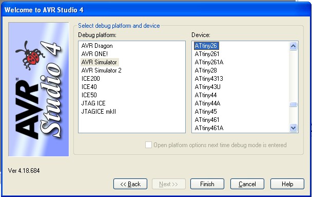
I haven’t made significant progress on my ATTiny26 code, but if you wish, you can select the ATMega32 microcontroller/AVR Simulator and try out the code from my Binary Clock.
The debugger is pretty cool, besides stepping through the code, you can also view register states and modify variables on the fly.
Enjoy 🙂
